Design Mordern Highrise Reinforced Concrete Structures – Hiroyuki Aoyama (KENCT0001)
0 VND
Tác giả: Hiroyuki Aoyama – University of Tokyo, Japan
Số trang: 462 trang
Định dạng file: pdf
Link tải sản phẩm:
Password giải nén nằm ở cuối phần mô tả.
Design Mordern Highrise Reinforced Concrete Structures – Hiroyuki Aoyama, CONTENTS:
Chapter 1 RC Highrise Buildings in Seismic Areas
1.1. Evolution of RC Highrise Buildings
1.1.1. Historic Background
1.1.2. Technology Examination at the Building Center of Japan
1.1.3. Increase of Highrise RC and the New RC Project
1.2. Structural Planning
1.2.1. Plan of Buildings
1.2.2. Structural Systems
1.2.3. Elevation of Buildings
1.2.4. Typical Structural Members
1.3. Material and Construction
1.3.1. Concrete
1.3.2. Reinforcement
1.3.3. Use of Precast Elements
1.3.4. Preassemblage of Reinforcement Cage
1.3.5. Re-Bar Splices and Anchorage
1.3.6. Concrete Placement
1.3.7. Construction Management
1.4. Seismic Design
1.4.1. Basic Principles
1.4.2. Design Criteria and Procedure
1.4.3. Design Seismic Loads
1.4.4. Required Ultimate Load Carrying Capacity
1.4.5. First Phase Design
1.4.6. Second Phase Design
1.4.6.1. Calculation of Ultimate Load Carrying Capacity
1.4.6.2. Ductility of Girders
1.4.6.3. Column Strength and Ductility
1.4.6.4. Beam-column Joints
1.4.6.5. Minimum Requirements
1.4.6.6. Imaginary Accident
1.4.7. Experimental Verification
1.5. Earthquake Response Analysis
1.5.1. Linear Analysis
1.5.2. Nonlinear Lumped Mass Analysis
1.5.3. Nonlinear Frame Analysis
1.5.4. Input Earthquake Motions
1.5.5. Damping
1.5.6. Results of Response Analysis
1.6. For Future Development
1.6.1. Factors Contributed to Highrise RC Development
1.6.2. Need for Higher Strength Materials
Chapter 2 The New RC Project
2.1. Background of the Project
2.2. Target of the Project
2.3. Organization for the Project
2.4. Outline of Results
2.4.1. Development of Materials for High Strength RC
2.4.2. Development of Construction Standard
2.4.3. Development of Structural Performance Evaluation
2.4.4. Development of Structural Design
2.4.5. Feasibility Studies for New RC Buildings
2.5. Dissemination of Results
Chapter 3 New RC Materials
3.1. High Strength Concrete
3.1.1. Material and Mix of High strength Concrete
3.1.1.1. Cement
3.1.1.2. Aggregate
3.1.1.3. Chemical Admixtures
3.1.1.4. Mineral Admixtures
3.1.1.5. Mix Design
3.1.2. Properties of High Strength Concrete
3.1.2.1. Workability
3.1.2.2. Standard Test Method for Compressive Strength
3.1.2.3. Mechanical Properties
3.1.2.4. Drying Shrinkage and Creep
3.1.2.5. Durability
3.1.2.6. Fire Resistance
3.2. High Strength Reinforcing Bars
3.2.1. Reinforcement Committee
3.2.2. Advantages and Problems of High Strength Re-bars
3.2.3. Relationship of New Re-bars to Current JIS
3.2.4. Proposed Standards for High Strength Re-bars
3.2.4.1. General Outlines
3.2.4.2. Specified Yield Strength
3.2.4.3. Strain at Yield Plateau
3.2.4.4. Yield Ratio
3.2.4.5. Elongation and Bendability
3.2.5. Method of Manufacture and Chemical Component
3.2.6. Fire Resistance and Durability
3.2.6.1. Effect of High Temperature
3.2.6.2. Corrosion Resistance
3.2.7. Splice
3.3. Mechanical Properties of Reinforced Concrete
3.3.1. Bond and Anchorage
3.3.1.1. Beam Bar Anchorage in Exterior Joints
3.3.1.2. Bond Anchorage in Interior Joints
3.3.1.3. Flexural Bond Resistance of Beam Bars
3.3.2. Lateral Confinement
3.3.2.1. Stress-strain Relationship of Confined Concrete .
3.3.2.2. Upper Limit of Stress in Lateral Reinforcement .
3.3.2.3. Buckling of Axial Re-bars
3.3.3. Concrete under Plane Stress Condition
3.3.3.1. Biaxial Loading Test of Plain Concrete Plate
3.3.3.2. Tests of Reinforced Concrete Plate under In-plane Shear
Chapter 4 New RC Structural Elements
4.1. Introduction
4.2. Beams and Columns
4.2.1. Bond-Splitting Failure of Beams after Yielding
4.2.2. Slab Effect on Flexural Behavior of Beams
4.2.3. Deformation Capacity of Columns after Yielding
4.2.4. Columns Subjected to Bidirectional Flexure
4.2.5. Vertical Splitting of Columns under High Axial Compression
4.2.6. Shear Strength of Columns
4.2.7. Shear Strength of Beams
4.3. Walls
4.3.1. Flexural Capacity of Shear-Compression Failure Type Walls
4.3.2. Deformation Capacity of Walls under Bidirectional Loading
4.3.3. Shear Strength of Slender Walls
4.4. Beam-Column Joints
4.4.1. Bond in the Interior Beam-Column Joints
4.4.2. Shear Capacity of 3-D Joints under Bidirectional Loading
4.4.3. Shear Capacity of Exterior Joints
4.4.4. Concrete Strength Difference between First Story Column and Foundation
4.5. Method of Structural Performance Evaluation
4.5.1. Restoring Force Characteristics of Beams
4.5.1.1. Initial Stiffness
4.5.1.2. Flexural Cracking
4.5.1.3. Yield Deflection
4.5.1.4. Flexural Strength
4.5.1.5. Limiting Deflection
4.5.1.6. Equivalent Viscous Damping
4.5.2. Deformation Capacity of Columns
4.5.2.1. Flexural Compression Failure
4.5.2.2. Bond Splitting Along Axial Bars
4.5.2.3. Shear Failure in the Hinge Zone after Yielding .
4.5.2.4. Shear Strength of Beams and Columns
4.5.3. Flexural Strength of Walls
4.5.4. Shear Strength of Beam-Column Joints
4.5.5. Connections of First Story Column to Foundation ….
4.5.5.1. Bearing Stress
4.5.5.2. Splitting Stress
4.5.5.3. Strengthening
4.6. Concluding Remarks
Chapter 5 Finite Element Analysis
5.1. Fundamentals of FEM
5.2. FEM and Reinforced Concrete
5.2.1. History of Finite Element Analysis of Reinforced Concrete
5.2.2. Modeling of RC
5.2.2.1. Two-Dimensional Analysis and Three-Dimensional Analysis
5.2.2.2. Modeling of Concrete
5.2.2.3. Modeling of Reinforcement
5.2.2.4. Modeling of Cracks
5.2.2.5. Modeling of Bond between Reinforcement and Con-crete
5.3. FEM of RC Members Using High Strength Materials
5.4. Comparative Analysis of RC Members Using High Strength Materials
5.4.1. Comparative Analysis of Beams, Panels and Shear Walls
5.4.2. Material Constitutive Laws
5.4.2.1. Uniaxial Compressive Stress-Strain Curves of Concrete
5.4.2.2. Compressive Strength Reduction Coefficient of Cracked Concrete
5.4.2.3. Confinement Effect of Concrete
5.4.2.4. Biaxial Effect of Concrete
5.4.2.5. Tension Stiffening Characteristics of Concrete .
5.4.2.6. Shear Stiffness of a Crack Plane
5.4.2.7. Cracking Strength
5.4.2.8. Stress-Strain Relationship of Reinforcement .
5.4.2.9. Dowel Action of Reinforcement
5.4.2.10. Bond Characteristics
5.4.3. Analytical Models and Analytical Results
5.4.3.1. Analysis of Beam Test Specimens
5.4.3.2. Analysis of Panel Specimens
5.4.3.3. Analysis of Shear Walls
5.4.3.4. Conclusions
5.5. FEM Parametric Analysis of High Strength Beams
5.5.1. Objectives and Methods
5.5.2. The Effect of Shear Reinforcement Ratio
5.5.3. Effects of Concrete Confinement Models with a Constant Value of pw σwy
5.5.4. Conclusions
5.6. FEM Parametric Analysis of High Strength Columns
5.6.1. Objectives and Methods
5.6.2. Analytical Results
5.6.3. Conclusions
5.7. FEM Parametric Analysis of High Strength Beam-Column Joints
5.7.1. Objectives and Methods
5.7.2. Comparison between Test and Analytical Results ….
5.7.3. Results of Parametric Analysis
5.7.4. Conclusions
5.8. FEM Parametric Analysis of High Strength Walls
5.8.1. Objectives and Methods
5.8.2. Outline of Research
5.8.3. Analytical Results and Discussions
5.9. FEM Parametric Analysis of High Strength Panels
5.9.1. Objectives and Methods
5.9.2. Analytical Results and Summary
Chapter 6 Structural Design Principles
6.1. Features of New RC Structural Design Guidelines
6.1.1. Earthquake Resistant Design in Three Stages
6.1.2. Proposal of Design Earthquake Motion
6.1.3. Bidirectional and Vertical Earthquake Motions
6.1.4. Clarification of Required Safety
6.1.5. Variation of Material Strength and Accuracy in Strength Evaluation
6.1.6. Structural Design of Foundation and Soil-Structure Interaction
6.2. Earthquake Resistant Design Criteria
6.2.1. Design Earthquake Intensity
6.2.2. Design Drift Limitations
6.2.3. Design Criteria
6.3. Design Earthquake Motion
6.3.1. Characteristics of Earthquake Motion
6.3.2. New RC Earthquake Motion
6.3.3. Relation to Building Standard Law
6.4. Modeling of Structures
6.4.1. Modeling of Structures
6.4.2. Relation of Model and Earthquake Motion
6.4.2.1. Fixed Base Model
6.4.2.2. Sway-Rocking Model
6.4.2.3. Soil-Foundation-Structure Interaction Model
6.5. Restoring Force Characteristics of Members
6.5.1. Dependable and Upper Bound Strengths
6.5.2. Member Modeling
6.5.3. Hysteresis
6.6. Direction of Seismic Design
6.6.1. Design Forces in Arbitrary Direction
6.6.2. Bidirectional Earthquake Input
6.6.3. Effect of Vertical Motion
6.7. Foundation Structure
6.8. Design Examples
6.8.1. 60-Story Space Frame Apartment Building . . . .
6.8.2. 40-Story Double Tube and Core-in-Tube Office Buildings
6.8.3. Mediumrise Office Buildings (15-Story Wall-Frame, 15-Story Space Frame, 25-Story Space Frame)
Chapter 7 Earthquake Response Analysis
7.1. Earthquake Response Analysis in Seismic Design ….
7.2. Structural Model
7.2.1. Three-Dimensional Frame Model
7.2.2. Two-Dimensional Frame Model
7.2.3. Multimass Model
7.2.4. Soil-Structure Model
7.3. Member Models
7.3.1. One-Component Model for Beam
7.3.2. Multiaxial Spring Model for Column
7.3.3. Wall Model
7.4. Nonlinear Response of SDF System
7.4.1. Displacement-Based Design Procedure
7.4.2. Correlation of Nonlinear Response to Linear Response
7.5. Numerical Analysis
7.5.1. Numerical Analysis of Equation of Motion
7.5.2. Release of Unbalanced Force
Chapter 8 Construction of New RC Structures
8.1. Introduction
8.2. Full Scale Construction Testing
8.2.1. Objectives
8.2.2. Outline of Construction Testing
8.2.3. Concrete Mix
8.2.4. Reinforcement Construction
8.2.5. Concrete Construction
8.2.6. Conclusion
8.3. Construction Standard for New RC
8.3.1. General Provisions
8.3.2. Reinforcement
8.3.3. Formwork
8.3.4. Concrete
8.3.4.1. General
8.3.4.2. Concrete Quality
8.3.4.3. Material
8.3.4.4. Mix
8.3.4.5. Manufacture of Concrete
8.3.4.6. Placing and Surface Finishing
8.3.4.7. Curing
8.3.4.8. Compressive Strength Inspection
Chapter 9 Feasibility Studies and Example Buildings
9.1. Feasibility Studies
9.1.1. Highrise Flat Slab Buildings
9.1.2. Megastructures
9.1.2.1. OP200 Straight Type
9.1.3. A Box Column Structure for Thermal Power Plant
9.2. Example Buildings
Design Mordern Highrise Reinforced Concrete Structures – Hiroyuki Aoyama
Password: CM9yK@22
| Brand | ebookxaydung English |
|---|
Hãy là người đầu tiên nhận xét “Design Mordern Highrise Reinforced Concrete Structures – Hiroyuki Aoyama (KENCT0001)” Hủy
Sản phẩm tương tự
Kết cấu nhà cao tầng (E)
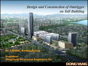
Design and Construction of Outrigger on Tall Building (KENCT0008)
Reinforced Concrete Structure Book
High Strength Concrete to Singapore Standard CP 65 – BCA Academy (KEBT0012)
Kết cấu nhà cao tầng (E)
Reinforced Concrete Design of Tall Buildings – Bungale S. Taranath (KENCT0005)
Kết cấu nhà cao tầng (E)
Structural Analysis and Design of Tall Buildings Steel and Composite Construction (KENCT0006)
Vật liệu xây dựng tiếng Anh
Kết cấu nhà cao tầng (E)
High-Rise Manual Typology and Design, Construction and Technology – Johann Eisele (KENCT0002)
Reinforced Concrete Structure Book
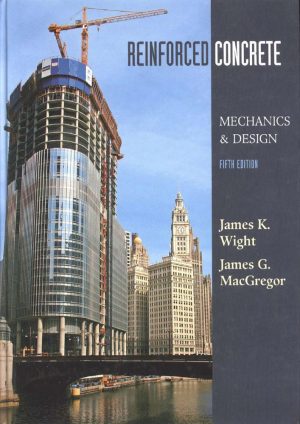
Reinforced Concrete Mechanics and Design – James K. Wight (KEBT0025)
Kết cấu nhà cao tầng (E)
Tall building design steel, concrete, and composite systems – Bungale S. Taranath (KENCT0007)






Đánh giá
Chưa có đánh giá nào.